Bend CAM
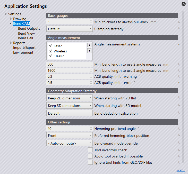
Back-Gauges
Min.thickness to always pull-back (mm) - This setting allows you to enter a value in mm of automatic withdrawal of the back gauges when the sheet thickness entered is reached.
Clamping Strategy - This is used to set how the back gauges are to stop on the workpiece.
The following selection options are available:
Default - The back gauges stop for each bend in the manner considered best by the software.
Stop + Stop - The straight surfaces of both back gauges stop against the workpiece.
Clamp + Stop - One back gauge clamps the workpiece and the other back gauge stops it with its straight surface.
Angle Measurement
Angle measurement is for Trumpf machines only. Using the angle measuring systems from the Automatically Controlled Bending family means even the first part in a series turns out perfect. Sensors determine the actual angle together with the spring back and guide the ram to achieve the desired angle. In this section, settings for ACB on the machine can be entered.
Angle Measurement Systems
Laser - Tick this option if the machine has an ACB Laser. ACB Laser is where a laser projects a line onto the sheet and a camera detects the angle.
Wireless - Tick this option if the machine uses ACB Wireless. ACB Wireless is sensor disks integrated into the upper tool.
Classic - Tick this option if the machine uses ACB Classic.
Min. Bend length to use 2 angle measures - This option is the minimum length of the fold to take two measurements to ensure the correct angle during folding. This can be between 50 > 4000 millimetres.
Min. bend length to use 3 angle measures -This option is the minimum length of the fold to take three measurements to ensure the correct angle during folding. This can be between 50 > 4000 millimetres.
ACB laser sensor park position - This is the resting position of the Laser Sensor.
ACB quality limit - warning - This is the limit which will generate a warning when measuring the part such as a fudge factor. If it is in the specific range, then it will file a warning.
ACB quality limit - error - This is the limit which will generate an error when measuring the part such as a fudge factor. It will file an error if it is in the specific range.
Geometry Adaptation Strategy
If a 2D or 3D file is edited in the software, the bend radii and the bend deduction are checked. Various processing strategies are executed depending on what strategies were selected for modifying the workpiece in the Easy Programming settings. If the decision was set to interactive, then the Adapt Geometry dialogue will be shown.
When starting with a 2D flat:
Ask each time - When navigating from a 2D part to bending, using this setting will automatically display the Adapt Geometry dialogue. This will give options of retaining the flat size, retaining the 3D dimensions or not changing anything, making this feature very interactive and user lead.
Keep 3D dimensions - This option changes the unfolding, which then must be saved manually. This strategy is used if the blank has not yet been cut.
Keep 2D dimensions - This option will mean the bend radius and the bend deduction are adjusted to the existing unfolding; the bending line remains in the same place. This will change the side length of the part. The unfolding is not changed. This strategy is used if the blank has already been cut to size.
No adjustments - Using this option will mean bend radius and bend deduction remain unchanged. The part is displayed with the correct dimensions in 3D, but the shown bend radii do not correspond to the actual bend radii. The dimension of each workpiece bend can change.
When starting with a 3D model:
Ask each time - When navigating from a 3D part to bending, using this setting will automatically display the Adapt Geometry dialogue. This will give options of retaining the flat size, retaining the 3D dimensions or not changing anything, making this feature very interactive and user lead.
Keep 3D dimensions - This option changes the unfolding, which then must be saved manually. This strategy is used if the blank has not yet been cut.
Keep 2D dimensions - This option will mean the bend radius and the bend deduction are adjusted to the existing unfolding; the bending line remains in the same place. This will change the side length of the part. This strategy is used if the blank has already been cut to size.
No adjustments - Using this option will mean bend radius and bend deduction remain unchanged. The part is displayed with the correct dimensions in 3D, but the shown bend radii do not correspond to the actual bend radii. The dimension of each workpiece bend can change.
Bend deduction calculation - This option makes it possible to force the K-Factor method to be used. This setting can be set in the Application Defaults or can be adjusted for each machine individually.
Note: For non-Trumpf machines, K-Factors are used always; the Trumpf bend computations are only available for Trumpf press brakes.
BG-left variant - Depending on the variant BG used, the NC code will be modified to represent this.
BG-right variant - Depending on the variant BG used, the NC code will be modified to represent this.
Other Settings
Hemming pre-bend angle - This option can edit the hem pre-bend angle between 10° > 60°. The default is 40° since that is the recommended hemming pre-bend angle for most manufacturers. It is set to 30° for all the Trumpf machines, in all the various editions.
Bend-guard mode override - Setting this to auto-compute (the default), Bend will compute a bend-guard mode for each bend. However, you can force the bend-guard mode to one of the options for it to just use that one, regardless of whether it is appropriate or not.
| You can also override this setting for each machine, by setting it up in Machine Defaults, instead of Application Settings. |
Machine table position - This setting has 3 options for the table position:
-
Removed
-
Down
-
Up
Tool inventory check - Enabling this option will show tool segments which may be needed for the workpiece to be bent. Insufficient inventory markers will be displayed.
Avoid tool overload if possible - Turning this option on will ensure a tool overload is avoided. Even if a tool with a higher priority would work on the part, a lower-priority tool will be used instead to avoid overload issues.
Ignore tool hints from GEO/DXF files - Enabling this option will ignore any information found on a DXF/GEO file regarding which tooling is to be used.